Building the Robot Chassis
Introduction
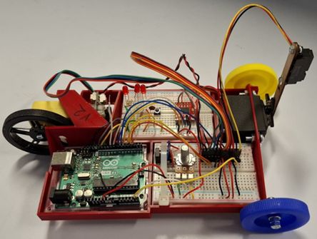
The system described in this section is the configuration that the author used during the development of the Introduction to Arduino exercises for this module, as shown in
Note
Many of the pictures in this Mechanical Component Assembly section were taken during the prototyping phase of the system design and feature a slightly earlier version of the robot chassis. As a result, there may be slight differences compared to the robot chassis in your kit, but the procedures described in this documentation are all for the final chassis design.
Info
For those of you that are not familliar with breadboard circuits, Sparkfun have in intersting article on
Adding the mechanical components to the chassis
This section covers the assembly of the mechanical system; a later section will cover the assembly of the electronic circuitry.
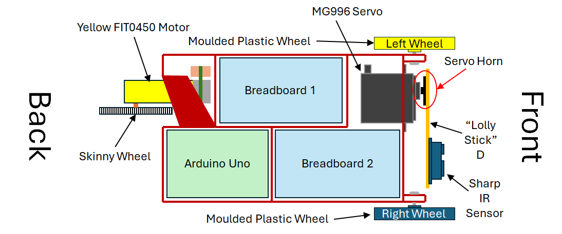
Due to overlapping parts, certain elements of the robot must be constructed in the order described below. See
- Attach the yellow FIT0450 motor to the back of the chassis
- Attach the skinny wheel to the motor
- Attach the cheap plastic wheels to the front of the chassis
- Attach the MG996 servo to the front of the chassis
- Attach the IR sensor to Lolly Stick D
- Attach the lolly stick to the servo horn
- Attach the assembled lolly stick (with the IR sensor and servo horn) to the servo shaft.
Attaching the FIT0450 and Skinny wheel
This is the most awkward component to attach to the chassis, as the motor must be maneuvered to slide into its final location and screw into place. The procedure for assembly is as follows:
- Push 2x M3x30 through the motor, from the brass shaft side.
- Carefully insert the motor into the chassis and manipulate it so that the screws are aligned with the screw holes in the chassis sidewall.
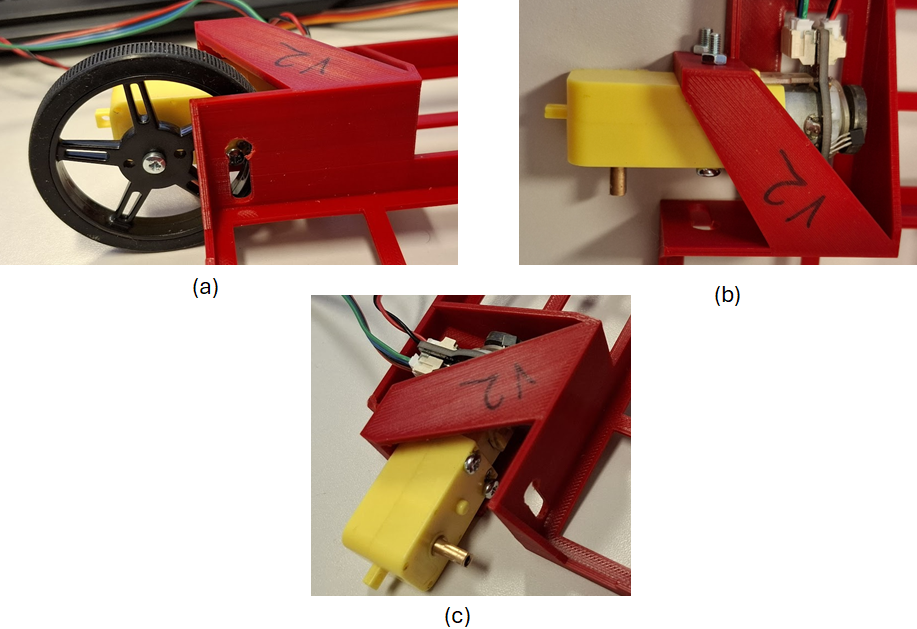
- Insert a screwdriver through the access holes in the chassis, push the screws through, and secure the motor using 2× M3 nuts, as shown in
Fig 3b and c . - Push the skinny wheel onto the motor shaft and use an M3x6 machine screw to fasten fasten it in place, as shown in
Fig 3a .
A video of this process is provided in
Note: This video has no commentary
Note: Skinny Wheels May need drilling out
The M3 mounting hole on some of the narrow wheels is too small and will need to be drilled out to 3 mm. Please see a member of the lab technical team during your lab session if this is the case.
Attaching the Moulded Plastic wheels
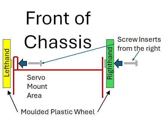
The moulded Plastic wheels attach to the robot chassis as shown in
Do this Before Attaching The MG996 Servo
These wheels must be attached before the servo, as the servo blocks access to the screw heads for the left wheel.
Attaching the Left-Hand Moulded Plastic Wheel
The left-hand molded plastic wheel is located next to the servo at the front of the robot, and it should be attached first. To attach this wheel, you will need an M3×20 mm bolt and an M3 Nyloc nut. The molded plastic wheels attach to the lugs at the front of the robot chassis.
The bolt for this wheel Must be inserted from between the lugs, with the bolt head in front of the rectangular servo hole. This ensures the servo mounting hole is not obstructed, allowing the servo to be installed correctly.
Note: This video has no commentary
Attaching the Right-Hand Moulded Plastic Wheel
The right-hand molded plastic wheel is located opposite the servo at the front of the robot, and it should be attached second. To attach this wheel, you will need an M3×20 mm bolt and an M3 Nyloc nut.
The presence of the left-hand wheel makes inserting the bolt from between the lugs difficult; therefore, we advise inserting the screw from the outside of the lugs, placing the nut on the inside.
Note: This video has no commentary
Note on wheel screw tightness
When securing the molded plastic wheels, ensure that you tighten the Nyloc nut sufficiently to prevent excessive wobble while still allowing the wheel to spin freely.
Attaching the MG996 Servo
Attach the moulded plastic wheels before the MG996 Servo
You must attach both plastic wheels before mounting the MG996 servo. Otherwise, the MG996 servo body will block access to the molded plastic wheel screws.
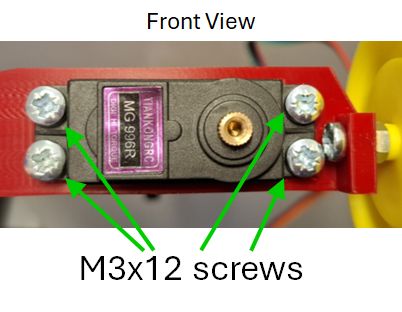
The MG996 servo is attached to the robot chassis using 4× M3×12 mm screws, as illustrated in
Note: This video has no commentary
Note: The hole for the servo has been modified since this video was filmed
For structural strength and 3D-printing yield, the servo mounting cutout on many chassis models is slightly tighter than shown in the video. With a little maneuvering, the servo will fit into the rectangular cutout.
Also note: All servo mounting hardware has been standardized to M3×12 mm screws, unlike the hardware shown in the video.
Assembling the Lolly Stick D Assembly
The lolly stick assembly consists of the Sharp IR sensor, a laser-cut plywood linkage, and a servo horn for the MG996 servo, as shown at the bottom of
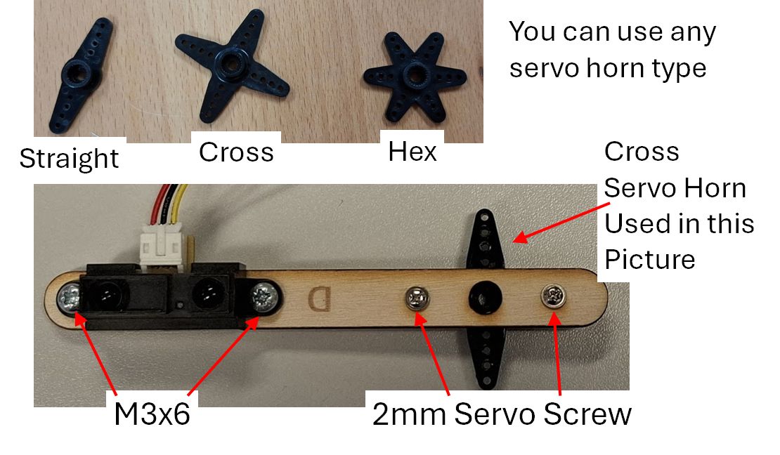
Note: You can use any of the servo horns shown at the top of
We recommend assembling the lolly stick as shown in
The IR sensor is secured to the lolly stick using 2× M3×6 mm screws and 2× M3 nuts, as shown in
The servo horn is attached to the lolly stick using 2× 2×8 mm Phillips head flange screws.
Warning: Sharp Screws
The pointed ends of the flange screws will protrude through the opposite side of the servo horn. Handle this assembly carefully to avoid minor injuries from the exposed tips.
Attaching the Lolly Stick D Assembly to the Servo
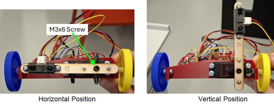
The servo horn pushes onto the MG996 servo shaft and is secured in position using an M3×6 mm screw. Once attached, verify that the lolly stick can rotate smoothly between the horizontal and vertical positions, see
Info
This assembly will need to be repositioned at the start of the "Control of the Standard Servo" exercise to ensure it is calibrated correctly for the task.
Electronic Component Layout and Connections
The layout of the electronic components on the breadboard is entirely up to you; however, the following sections illustrate how they were arranged during the design and prototyping stages of these exercises. The author recommends following this layout because it matches the example code provided for the exercises and represents a proven design.
The connections for each exercise are discussed in more detail in the
Breadboard layouts
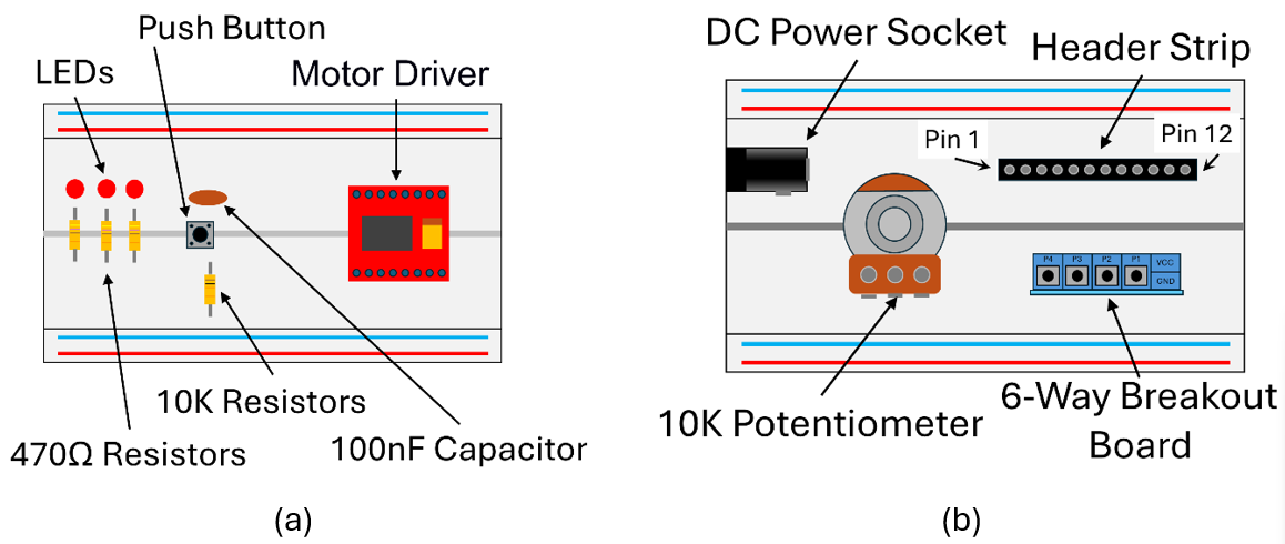
We suggest placing the components on the two breadboards as shown in
- Breadboard 1: The LEDs, push button, and motor driver board.
- Breadboard 2: The DC power inlet socket, 10 kΩ potentiometer, and a 12-way header strip (used to connect the motor power, encoder, MG996 servo, and Sharp IR sensor).
The location of breadboard 1 and breadboard 2 in the robot chassis are illustrated in
External DC Power Socket and Connection
Some of the robot systems draw too much power to be supplied directly from the Arduino via the USB connection. If you power the MG996 servo or the DC motor directly from the Arduino, you may exceed the current limits of the +5 V rail. This can cause erratic behavior, such as the Arduino intermittently restarting—a condition known as a
To overcome this issue, we will use an external DC power supply to provide additional current for power-hungry components, specifically the MG996 servo and the DC motor driver board. To facilitate this, you will add a DC power connector to your robot system, as shown in
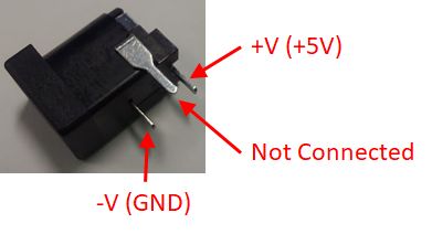
In previous years, student setups experienced issues with the DC power connector slipping out of the breadboard. To significantly reduce the chances of this happening, a cable tie can be used to strap the DC connector down to Breadboard 2, as illustrated in
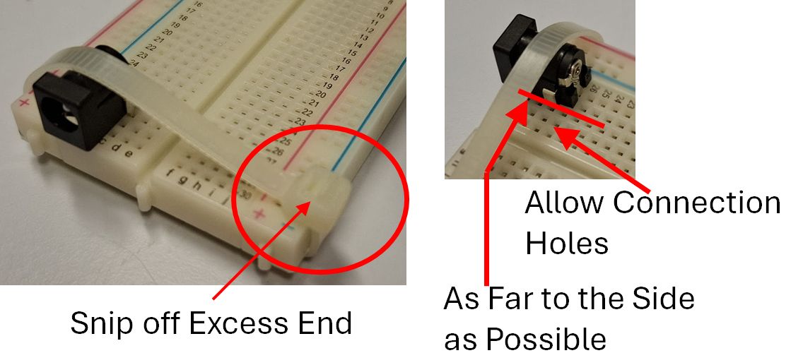
Note
Ensure that the cable tie is pulled tight around the board so that the connector cannot move before trimming the excess end.
The following section provides important details concerning the two different power supplies on the breadboards and MUST be read before continuing.
Arduino and External Power Supplies Lines
There are two +5V power supplies on the robot chassis:
- The +5V supply from the Arduino.
- The external +5V from the AC-DC Plug-in Power adaptor.
UNDER NO CIRCUMSTANCE should the +5V line from the Arduino be connected to the external 5V line. You must, however, connect all the GND (ground) lines of these power supplies - and other systems - to a common GND net/node on your robot chassis to ensure that all the working from the same reference voltage.
The external +5V should only be connected to the Vm connection of the motor drive board and the V+ power connections of any servo used on your system. The Arduino +5V should be used for the Vcc connection of the motor drive board and any other connection requiring +5V, that are not powered by the external +5V supply.
Danger: You can destroy your Laptop motherboard if you get this wrong
If you connect the +5 V supply of the Arduino and the external power supply together, you risk destroying your laptop's motherboard by sending a high voltage/current transient up the USB lead when the servo or DC motor operates.
Read the Disclaimer document before proceeding.
The University and MEE take no responsibility for damaged laptops due to this issue. We recommend using the University IT equipment to mitigate damaging your personal equipment.
At this point, you may have noticed how strongly we emphasize NOT connecting the external +5 V line to the Arduino +5 V line. This is because we want to avoid having to tell anyone that we cannot pay for repairs to their personal IT equipment... It is not a fun conversation to have!!
Suggested Circuit Layouts for the Exercises
The electronic system for the robot can be built incrementally as required for each exercise. The exercises are designed so that you only ever need to add components to the system, with later exercises building upon the work of previous ones. This means no circuitry needs to be removed between exercises.
Before starting any of the following exercises, you will need to add these additional elements to your robot circuit.
- Basic: LED Pattern
- No extra circuitry is required for the Calibration of Potentiometer Angle Exercise. This uses the potentiometer from the LED Pattern Exercise.
- Basic: IR Sensor Measurement + Graph
- Basic: Externally Powered Servo
- Basic: DC Motor
- Basic: Encoders and Motor
Note: Advanced Exercises
The advanced exercises do not require any additional circuit building. They build directly on the circuit constructed for the final Basic Exercise: Encoders and Motor.
Note on the circuit layout diagrams in the following sections
The circuit layout diagrams in the following sections were created using different drawing tools. As a result, some components and connections may not line up perfectly. Please use these diagrams alongside the accompanying figures and tables to get a clear, complete picture of how to assemble the circuit.
Circuit Layout for the LED Pattern and Calibration of Potentiometer Angle Exercises
The following circuit layout is sufficient to complete both the LED pattern exercise. This section illustrates the layout and connections for the three LEDs and their associated resistors, the push button, and the potentiometer, as shown in
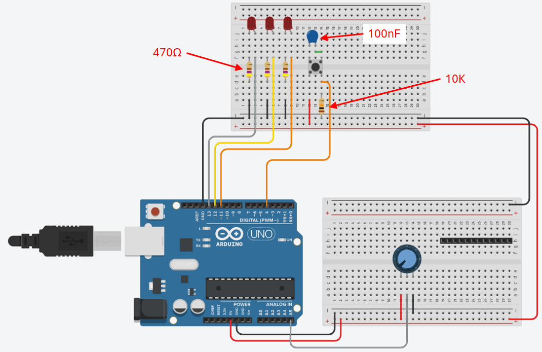
The additional components required for this exercise (in addition to the Arduino and two breadboards) are shown in
- 3x LED
- 3x 470Ω resistor
- Tactile button
- 100nF capacitor
- Potentiometer
- 12-way header
| Arduino Pin: | Description: |
|---|---|
| DIO 4 | Button |
| DIO 11 | LED 1 |
| DIO 12 | LED 2 |
| DIO 13 | LED 3 |
| A5 | Potentiometer Input |
Circuit Layout for the IR Sensor Exercise
This section illustrates how to connect the Sharp IR sensor into the circuit for the IR Sensor Measurement and Graph exercise, as shown in
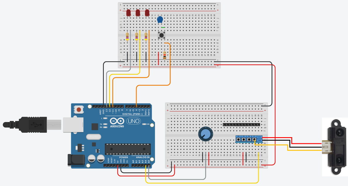
Extra parts required for this configuration:
- Sharp IR Sensor
- Sharp IR Sensor cable
- 6-way Screw Terminal Breakout Board
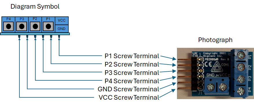
The Sharp IR sensor interfaces with the breadboard using the 6-way screw terminal breakout board shown in
| Arduino Pin: | Description: |
|---|---|
| A4 | IR Sensor Output |
The Sharp IR sensor cable has stripped wire ends that should be connected to the 6-way screw terminal breakout board according to the pinout in
| IR Sensor Wire: | Description: | Breakout Board Terminal: |
|---|---|---|
| Yellow | IR Sensor Output | P1 |
| Red | +5V Power | VCC |
| Black | 0V Power (GND) | GND |
Circuit Layout for the Externally Powered Servo Exercise
The servo will be used in the
Warning
UNDER NO CIRCUMSTANCE should the +5V External power supply be connected to the +5V Arduino supply. You must, however, connect all the GND lines of these power supplies, and other systems, to a common GND net/node on your robot chassis to ensure that all components share the same reference voltage.
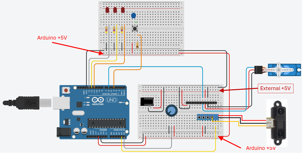
In addition to the Arduino and two breadboards, the extra components required for this exercise, shown in
- DC Servo (SG90 for the
initial servo exercise and final assessed Exercise) - DC power socket
Note
The
| Arduino Pin: | Description: |
|---|---|
| DIO 6 | Servomotor Signal Pin |
Circuit Layout for the DC Motor Exercise
The DC motor exercise requires both the TB6612FG and the DC motor to be wired into the circuit, as illustrated in
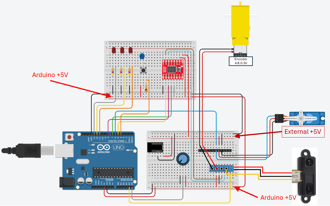
Extra parts required for this configuration:
- TB6612FG driver board
- DC motor
- DC motor power cable
Due to the orientation of the TB6612FNG board on the robot chassis, we will use Channel B for these exercises. The TB6612FNG driver board is shown in
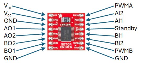
| Arduino Pin: | Description: |
|---|---|
| DIO 5 | PWM Signal Pin |
| DIO 7 | BI1 Signal Pin |
| DIO 8 | BI2 Signal Pin |
Note
All GND pins are connected internally on the TB6612FNG breakout board; therefore, only a single GND connection to the power system is required.
The DC motor power terminals are connected through the
Circuit Layout for the Encoders and Motor Exercise
The final part of the circuit to connect is the motor encoder to the Arduino, as illustrated in
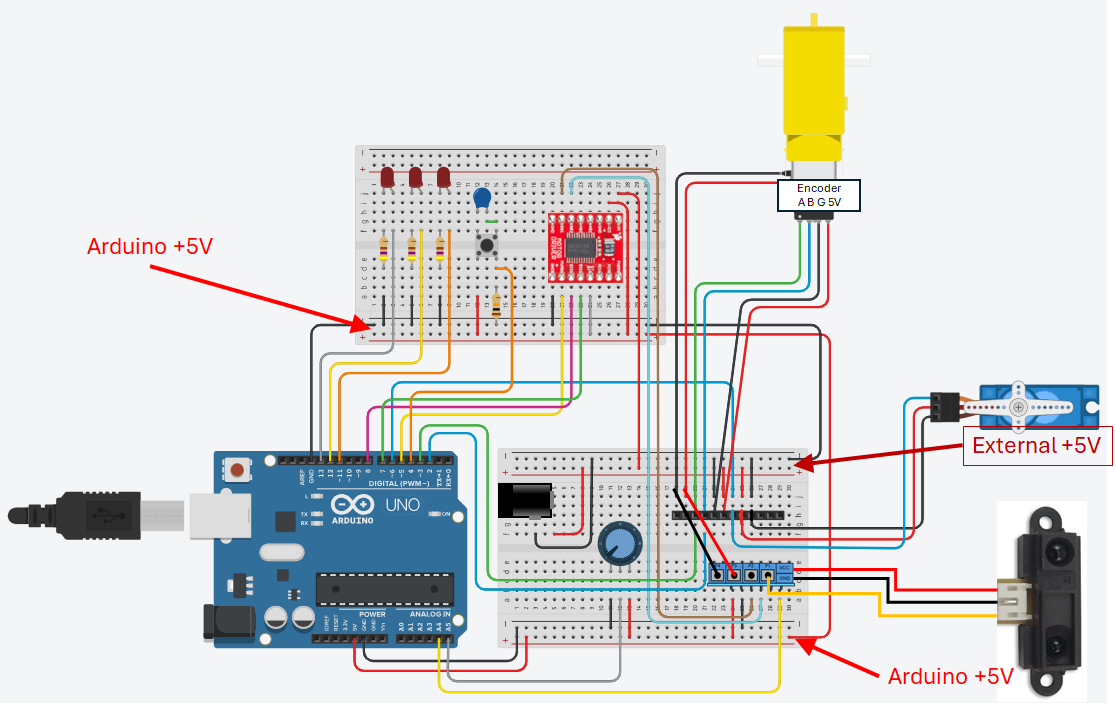
Extra parts required for this configuration:
- DC motor encoder cable
| Arduino Pin: | Description: |
|---|---|
| DIO 2 | Encoder B Signal |
| DIO 3 | Encoder A Signal |
The 12-Way Header Connections
The 12-way header connector provides a convenient method for interfacing key system components—the motor, encoder, servo, and IR sensor—to the breadboard for easy integration with the rest of the electrical system. A summary of the connections used during development is provided in
Note
During the writing of this document, a 6-way screw terminal header was added to the assembly to replace some of the 12-way header connections. As a result, several of the 12-way header connections listed in