Closed Loop Control Using the Encoder as a Feedback Sensor
GTA Marking
This is an assessed Exercise. When you have completed the
Before Continuing
Before starting these exercises, you should ensure that you have completed all the
Introduction
In this exercise, you will implement a program to drive the robot chassis forward and backward through a predefined sequence of distance setpoints. The system must operate under closed-loop control using a Proportional-Integral (PI) controller with quadrature motor encoders providing position feedback.
Your firmware architecture should incorporate a Finite State Machine (FSM) to govern operational state transitions and sequence progression.
The following video demonstrates the closed-loop tracking response and sequential state progression of the completed system:
A Simple Finite State Machine
A Finite State Machine (FSM) is a software architecture design pattern used to govern system behavior based on discrete states and event-driven conditions. We will only consider their use in the most simple form.
An FSM defines operation using three primary elements:
- States: The operational modes or conditions of the system at any given moment.
- Triggers / Events: Inputs or conditions that occur within the system or environment.
- State Transition Conditions: Logical criteria evaluated to determine when the system transitions from one active state to another. A system can only switch states when its associated transition conditions are fully satisfied.
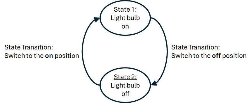
Consider a simple two-state system: a light bulb connected to an ON/OFF toggle switch. The bulb can exist in only one of two states: ON or OFF. Moving the switch to the "OFF" position triggers the transition from State 1 (ON) to State 2 (OFF). Conversely, moving the switch to the "ON" position fulfills the condition to transition from State 2 (OFF) back to State 1 (ON).
This sequential operation is represented in the state transition diagram shown in
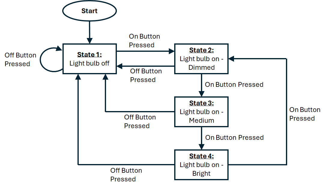
We can extend this concept to a four-state light dimmer system with variable intensity outputs: OFF, DIMMED, MEDIUM, and BRIGHT. System transitions are controlled by two pushbuttons: ON and OFF.
- Power-On Default: Upon system reset, the state machine automatically initializes to State 1 (OFF).
- ON Button Press: Increments brightness level, cycling sequentially through active states (State 2: DIMMED \(\rightarrow\) State 3: MEDIUM \(\rightarrow\) State 4: BRIGHT \(\rightarrow\) State 2: DIMMED, etc).
- OFF Button Press: Overrides current activity and forces an immediate transition back to State 1 (OFF) from any active state.
This operation is illustrated in the state transition diagram shown in
This is a very simple state machine example for a 2 state system. We can extend this idea to a system which varies the light level output between: off, dimmed, medium and bright, with state transitions defined by two buttons: on and off. When the system starts, the system automatically switches to state 1: off. The on button is used to switch the light on and toggle the system states between states 2, 3 and 4, to adjust the brightness, whereas if the off button is pressed, the system will always return to the off state. This operation is summarised on the state transition diagram,
To implement the switch statement, where each case label defines the specific execution logic and transition checks for a single operational state, such that:
#define onPin 1       // On button pin
#define offPin 2      // Of button pin
#define outputPin 13  // LED output Pin

int state = 1;        // Initialise the state variable to 1
int brightness = 0;   // 0 = Off, 100 = Dimmed, 175 = Medium, 255 = Bright

int onButton = 0;
int offButton = 0;

void setup() {
  pinMode(onPin, INPUT);
  pinMode(offPin, INPUT);
}

void loop() {

  // Read the states of the buttons
  onButton = digitalRead(onPin);
  offButton = digitalRead(offPin);

  // Process the state machine
  switch (state) {
    case 1:
      // Process the current state operations
      brightness = 0;
      analogWrite(outputPin,brightness);

      // Check for state transition conditions
      if (onButton == 1) state = 2;  // if on button pressed, change to state 2

      break;

    case 2:
      // Process the current state operations
      brightness = 100;
      analogWrite(outputPin,brightness);

      // Check for state transition conditions
      if (onButton == 1) state = 3;  // if on button pressed, change to state 3
      if (ofButton == 1) state = 1;  // if off button pressed, change to state 1

      break;

    case 3:
      // Process the current state operations
      brightness = 175;
      analogWrite(outputPin,brightness);

      // Check for state transition conditions
      if (onButton == 1) state = 4;  // if on button pressed, change to state 4
      if (ofButton == 1) state = 1;  // if off button pressed, change to state 1

      break;

    case 4:
      // Process the current state operations
      brightness = 255;
      analogWrite(outputPin,brightness);

      // Check for state transition conditions
      if (onButton == 1) state = 2;  // if on button pressed, change to state 2
      if (ofButton == 1) state = 1;  // if off button pressed, change to state 1

      break;

    default:
    // Process the unknown state operations
      brightness = 0;
      analogWrite(outputPin,brightness);
      state = 1; // return to state 1
      break;
  }

  delay(1000);
}
Note
The above code is functional, but the handling of the button presses is poor. This has been provided as a simple example of how to implement a simple state machine, with multiple state, and state transition events.
Assessed Exercise
In this exercise, you will develop firmware to move the robot chassis forward and backward through a sequence of designated target positions.
- Closed-Loop PI Position Control: Implement a Proportional-Integral (PI) control loop that uses quadrature motor encoder counts as position feedback. Open-loop time-based movement (e.g., driving motors forward for a fixed duration) is strictly prohibited.
- Finite State Machine Architecture: Use a Finite State Machine (FSM) to manage sequential system behaviour and switch target position setpoints.
- Non-Blocking Execution & Timing: All loop timing, interval scheduling, and state transitions must be executed using non-blocking timing with millis(). The use of blocking functions like delay() or delayMicroseconds() in your execution loop is strictly forbidden.
Design Hints & Recommended Tuning
- State-Driven Position Setpoints: The FSM states represent target position setpoints (\(r[k]\)) supplied to the PI controller. Evaluate and update the position control loop within the state machine execution block.
- Deterministic Sampling Period: Set the PI controller loop sampling period to \(\Delta T = 10\,\text{ms}\) (\(100\,\text{Hz}\)) using non-blocking millis() timing logic.
-
Initial Controller Tuning: Begin tuning with the following gain parameters:
\[K_p = 4.0, \quad K_i = 0.0\]These baseline parameters produce an underdamped (oscillatory) system response, allowing you to observe closed-loop transient dynamics before fine-tuning integral action.
Exercise Assessment
What we expect to see from your demonstration?
- When the robot is reset, there is a delay of 3 seconds before the system starts
- The robot should move forward 30cm
- When it has reached its destination, the robot should wait 2 seconds.
- The robot should move backward 15cm
- When it has reached its destination, the robot should wait 2 seconds.
- The robot should move forward 30cm
- When it has reached its destination, the robot should wait 2 seconds.
- The robot should move backward 45cm, returning to the start point.
- When it has reached its destination, the robot should wait 2 seconds, before repeating the above sequence.
You show the GTAs the following in your code:
- You have not used
delay()ordelayMicroseconds()functions to achieve the timing of the code - You have used a
switchstatement to achieve the state machine behaviour of the system - You are using a PI controller to control the position of the robot
Now Get Your Work Marked by a GTA
Once you have completed your code and are satisfied with its operation, you should show your work to a GTA for marking.