Interfacing the Incremental Encoder from the Gear Motor
GTA Marking
This is an assessed Exercise. When you have completed the Assessed Exercise, you should show your work to a GTA to get marked.
Prerequisite for this Exercise
Before starting this exercise, verify that you have completed the circuit on the robot chassis as illustrated in
Before you start this exercise, you should complete the
The following video is a quick demonstration of the final outcome from this exercise:
Introduction and Background
Rotary sensors measure the angular position and/or rotational speed of a rotating body (typically a shaft) using either analog or digital outputs. The term rotary encoder generally describes a digital rotational position sensor.
Rotary encoders fall into two primary categories:
- Absolute Position Encoders: Devices in this class output the exact angular position of the rotating shaft immediately upon power-up, without requiring an initial zero reference or homing sequence.
- Incremental Position Encoders: Devices in this class report relative changes in angular displacement from a starting reference point. Absolute position can only be determined if the system records a known initial start-up position or detects an explicit index pulse (Z-channel).
For additional background on encoder working principles, refer to the
Rotary speed can be measured directly using a rotary shaft encoder designed as a tachometer (though dedicated tachometers will not be covered further in this document). Alternatively, rotational speed (\(\omega\)) can be calculated from a position encoder by measuring angular displacement (\(\Delta\theta\)) over a known sampling time interval (\(\Delta t\)):
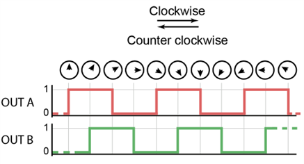
Sensing technologies for position encoders vary across designs, with optical and magnetic sensing being the two most common approaches. The incremental encoder integrated into the FIT0450 geared DC motor (included in your Mechatronics kit) is a magnetic quadrature encoder. Quadrature encoders output two channel square waves, designated Channel A and Channel B, which are phase-shifted relative to each other by \(90^\circ\), as illustrated in
Analogue Sensors vs. Digital Switch Sensors
An analogue sensor produces a continuous, variable output signal (such as a changing voltage level) that typically requires external signal conditioning or filtering before being processed by a microcontroller's ADC.
In contrast, a digital switch sensor incorporates internal signal-conditioning circuitry (e.g., Schmitt triggers or comparators) to directly output clean HIGH (\(5\,\text{V}\)) or LOW (\(0\,\text{V}\)) logic levels, enabling direct connection to digital GPIO pins.
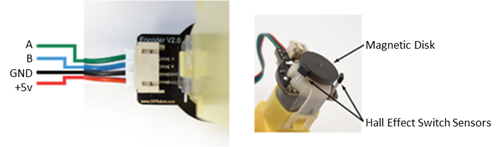
As the magnetic disc rotates, each transition of a north pole past a Hall-effect switch toggles the output logic state from 0 to 1 (and back to 0 when a south pole passes). This continuous transition produces a digital square wave at the output of each switch sensor. The encoder contains two outputs, Channel A and Channel B, corresponding to the two Hall sensors. The physical sensors are spatially positioned \(90^\circ\) electrically out of phase around the disc's circumference. Consequently, outputs A and B generate square waves offset by \(90^\circ\), as shown in
For the FIT0450 motor, the magnetic disc contains \(8\) pole pairs, yielding \(8\) full square-wave pulses per sensor for a single revolution of the motor armature shaft. Because the motor is fitted with a \(120:1\) reduction gearbox, one complete revolution of the main output shaft corresponds to:
Counting both rising and falling edges across both channels quadruples the available measurement resolution (\(960 \times 4 = 3,840 \text{ state transitions/rev}\)). Base pulse-counting accuracy without quadrature edge decoding corresponds to \(960 \text{ PPR}\), equivalent to:
At higher rotational speeds, encoder outputs generate high-frequency pulse trains. Polling pin states sequentially inside the standard Arduino loop() function is unreliable; if the microcontroller is executing other tasks during a pin transition, pulses will be missed, leading to cumulative position errors. To ensure reliable signal processing, encoder channels should be sampled using hardware interrupts. The microcontroller's interrupt module detects logic state changes on dedicated General Purpose Input/Output (GPIO) pins, temporarily pausing main thread execution to instantly run a specialized function known as an Interrupt Service Routine (ISR).
Reading a quadrature encoder relies on level-change interrupts configured on the microcontroller's digital input pins connected to Channels A and B. Whenever a logic-level transition occurs on either channel, the main execution thread is interrupted and the corresponding Interrupt Service Routine (ISR) is immediately executed. Consequently, processor tasks are temporarily paused to service the encoder event, preventing lost pulses.
In the case of reading the quadrature encoder, we use a level change interrupt on the pins of the microcontroller, attached to the quadrature encoder. Each time there is a level transition in either output A or B, the main code is interrupted and the ISR is run by the microcontroller. This means that whatever the microcontroller is busy doing, the execution is stopped to process the interrupt, and no pulses are lost.
Interrupts can be configured in multiple ways to track encoder outputs. Achieving maximum resolution (\(4\times\) decoding) requires configuring interrupts on both input pins, whereas using a single interrupt on one channel yields half the resolution (\(2\times\) decoding).
The dual-interrupt method, outlined in
| ROTATION: | OUTPUT A: | OUTPUT B: | Which ISR? | COUNT: |
|---|---|---|---|---|
| CW | 0→1 | 0 | A | +1 |
| 1 | 0→1 | B | +1 | |
| 1→0 | 1 | A | +1 | |
| 0 | 1→0 | B | +1 | |
| CCW | 0→1 | 1 | A | -1 |
| 1 | 1→0 | B | -1 | |
| 1→0 | 0 | A | -1 | |
| 0 | 0→1 | B | -1 |
The code snippet below provides a framework for configuring digital pins D2 and D3 on the Arduino Uno as interrupt-capable inputs. Using the attachInterrupt() function, these pins are assigned to their respective ISRs, ChannelA() and ChannelB(), which trigger on any state transition (CHANGE).
#define PINA 2 // A output of the  encoder attached to PIN 2 of the Arduino
#define PINB 3 // B output of the  encoder attached to PIN 3 of the Arduino

volatile long enc_count = 0; // Pulse count from the quadrature encoder

void setup(){
  // Initialize the A and B input pins
  pinMode(PINA, INPUT);
  pinMode(PINB, INPUT);

  // Attach interrupt to PINA. When the pin changes state, the function
  // channelA() is called.
  attachInterrupt(digitalPinToInterrupt(PINA),channelA, CHANGE);
  // Attach interrupt to PINB. When the pin changes state, the function
  // channelB() is called.
  attachInterrupt(digitalPinToInterrupt(PINB),channelB, CHANGE);

}

void loop() {
...
}

void ChannelA(){
...
}

void ChannelB(){
...
}
For a detailed technical description of the function, refer to the official Arduino attachInterrupt() Reference Guide.
The CHANGE interrupt mode is passed to attachInterrupt() to ensure an interrupt fires on both rising (\(0 \rightarrow 1\)) and falling (\(1 \rightarrow 0\)) signal edges on Channels A and B, maximizing pulse count resolution.
The volatile Keyword Qualifier
The enc_count global variable is declared with the volatile qualifier. Any variable modified within an ISR and read in the main loop must be qualified as volatile. This directs the compiler to load the variable from RAM rather than caching it in a CPU register, ensuring thread-safe reads during asynchronous interrupt events.
For further information, consult the Arduino volatile Reference Guide.
Arduino Hardware Interrupt Pin Allocation
On the Arduino Uno, hardware interrupts are available strictly on digital pins D2 (Interrupt 0) and D3 (Interrupt 1).
On the Arduino Mega 2560, pins D2, D3, D18, D19, D20, and D21 support external interrupts. Note that pins D20 (SDA) and D21 (SCL) cannot be used for interrupts if \(\text{I}^2\text{C}\) bus communication is active (though \(\text{I}^2\text{C}\) is not utilized by the sensors in this Mechatronics kit).
Before implementing closed-loop DC motor control, converts raw pulse counts into physical engineering units—such as output shaft revolutions or angular position (\(\theta\)). Calculate output shaft revolutions using:
To compute angular displacement in degrees (\(^\circ\)):
Quadrature Edge Counting & Resolution Scaling
The equations above assume a pulse count based on full square-wave cycles (\(1\times\) resolution). Because the provided dual-ISR framework triggers on every rising and falling edge across both channels (\(4\times\) quadrature state decoding), the total accrued edge count is four times higher.
Reading the Output of the Incremental Encoder
The aim of this exercise is to sample the rotary encoder position using interrupts and continuously output the accumulated position data to the Arduino IDE Serial Monitor.
Before proceeding, verify that all hardware wiring and pin connections comply with the specifications in the
The following code template below provides the foundation for reading the FIT0450 incremental encoder. This sketch is incomplete; you must apply the technical principles covered in the preceding theory sections to implement the missing logic during the assessed exercise below.
#define ENC_K [Insert the value for the FIT0450 Gearmotor] //Number of edges
//  per revolution of the output shaft
#define PINA 2 // A output of the quadrature encoder attached to PIN 2
#define PINB 3 // A output of the quadrature encoder attached to PIN 3

//These two variables are declared as volatile because they are updated
// within an ISR
volatile long encCount; // Pulse count from the quadrature encoder
volatile float wheelAngle; // Angle of the output shaft of the gear motor,
// attached to the wheel

// initialise the lastDisplay variable
long lastDisplay = 0;
#define delayDisplay 250

void setup() {
  Serial.begin(9600);
  pinMode(PINA, INPUT);

  // Attach interrupt to PINA. When the pin changes state, the function channelA()
  // function is called.
  attachInterrupt(digitalPinToInterrupt(PINA),channelA, CHANGE);

  // Attach interrupt to PINB. When the pin changes state, the function channelB()
  // function is called.
  attachInterrupt(digitalPinToInterrupt(PINB),channelB, CHANGE);

  encCount = 0;
  wheelAngle = 0;
}

void loop() {

  // Update the Serial Monitor every 250ms
  if (millis() >= lastDisplay + delayDisplay) {

    // update lastDisplay to the current millis() time
    lastDisplay = millis();

    // construct the serial monitor messages
    Serial.print("Encoder Pulse Count = ");
    Serial.print(encCount);
    Serial.print("Wheel angle = ");
    Serial.print(wheelAngle);
    Serial.println("°");
  }
}

void channelA() {
// Use if else statements to increment or decrement the encCount variable
// Use information in the table in the Encoder section of the The Rotary
// Position Encoder section of the laboratory Documentation.
// Focus on the table rows where Output A is changing
// Use digitalread() to acquire the states of PINA and PINB

  if([insert a logic statement here]) {
    if([insert a logic statement here]){
      encCount++; // Encoder rotating in one direction, e.g. clockwise
    }
    else {
    // Encoder rotating in the opposite direction, e.g. counter clockwise
    encCount--;
    }
  }
  else{
    if([insert a logic statement here]){
      encCount++; // Encoder rotating in one direction, e.g. clockwise
    }
    else {
    // Encoder rotating in the opposite direction, e.g. counter clockwise
    encCount--;
    }
  }

  //compute the angle of rotation of the wheel using the pulse count, encCount
  wheelAngle = ;

}
void channelB() {
  // Use function channelA() as a template
  // This time focus on the rows of the table where Output B is changing
}
Quadrature Edge Count vs. Pulse Count
This dual-interrupt implementation detects every rising and falling logic edge across both Channel A and Channel B signals (\(4\times\) quadrature edge decoding), rather than counting full square-wave pulses. Consequently, the accumulated count will be four times greater (\(4\times\)) than the raw pulse count.
Reading the Rotary Encoder Exercise
The aim of this exercise is to implement and verify rotary encoder signal acquisition prior to integrating DC motor actuation.
While this exercise is non-assessed, completing it is strongly recommended before attempting subsequent tasks, as it establishes the foundational pulse-counting functionality required for the
Procedure:
- Copy and paste the starter code template provided above into a new Arduino sketch.
- The ISR for Channel A, ChannelA(), is partially implemented. Complete the function by applying the state-evaluation logic defined in
Table 1 . - Based on your implementation of ChannelA(), write the corresponding logic for the ChannelB() ISR function.
- Modify the code to update and print the encoder values to the Serial Monitor every \(250\,\text{ms}\).
- Ensure that the ENC_K constant is set to the total number of digital edges per output revolution, rather than the raw pulse count.
- Upload the code to your Arduino board and manually rotate the motor wheel. Verify that the Serial Monitor outputs accurate, real-time positional data and correctly indicates direction changes.
Avoid Using the Delay() Function
For the timing of the serial monitor and other events, you should use the millis() method in the TwoInterruptEncoder.ino template file, and not use the delay() method.
Using blocking functions like delay() is bad practice in embedded software development; it freezes processor execution, delays non-interrupt loop tasks, and causes significant timing jitter in multitasking systems, preventing your code from executing in a deterministic manner.
Assessed Exercise
The aim of this exercise is to measure the angular position of the motor wheel using the quadrature encoder and control the motor actuation to position the wheel accurately across a sequence of target setpoints.
During this exercise, you are required to integrate your implementations from the following preceding tasks:
- The
Reading the Rotary Encoder Exercise , above - The
DC Motor: Assessed Exercise
Procedure:
Write a program that can rotate the wheel connected to the DC motor according to the following cycle:
- From an initial starting point, rotate the wheel 45° clockwise
- Wait for 1 second
- Rotate the wheel 45° anticlockwise (back to the starting position)
- Wait for 1 second
- Rotate the wheel 90° clockwise
- Wait for 1 second
- Rotate the wheel 90° anticlockwise
- Wait for 2 seconds, then repeat the sequence.
- On the serial monitor, you should display:
- The time in seconds from the start of the demo
- You should calculate this, not use the serial monitor time stamp
- The PWM output to the motor
- The shaft position of the motor in degrees.
- The time in seconds from the start of the demo
Non-Blocking Timing Requirements
Remember: do not use blocking functions such as delay() in your code. Implement non-blocking timing using the millis() function, as demonstrated in the TwoInterruptEncoder.ino template file above.
Exercise Assessment
What we expect to see from your demonstration?
- Demonstrate that you have fulfilled the requirements of the exercise with your working system.
- The rotational sequence for the output shaft as described above.
- An external power supply is used to power the motor circuit, (Vm on the driver board).
- Demonstration time in seconds, motor PWM value, control logic Boolean values to the driver board, and the motor shaft angle, are clearly labelled and displayed on the serial monitor.
- The serial monitor should update at a reasonable rate – 2 to 4 times a second.
Now Get Your Work Marked by a GTA
Once you have completed your code and are satisfied with its operation, you should show your work to a GTA for marking.
Extension Exercise: Reading multiple encoders efficiently. (Non-Assessed)
Formative Exercise
This extension exercise is non-assessed and formative. Completing this task is recommended, as the interrupt techniques covered here may be very useful for your group project.
The aim of this exercise is to implement Pin Change Interrupts (PCINT) on micro-controller I/O ports rather than relying exclusively on dedicated external interrupt pins (INT0/INT1).
Note: Pin Change Interrupts are a hardware feature specific to AVR microcontrollers (e.g., ATmega328P). Implementation details and register configurations may vary across different architecture families.
When controlling differential-drive or multi-axis mobile robots, multiple quadrature encoders must be sampled simultaneously. On the Arduino Uno, external hardware interrupts via attachInterrupt() are constrained strictly to digital pins D2 and D3. Upgrading to a larger development board—such as the Arduino Mega 2560—provides additional external interrupt pins, but scaling to higher encoder counts requires a more flexible architectural solution.
A scalable and hardware-efficient approach for acquiring two or more quadrature encoders is utilizing Pin Change Interrupts (PCINT). On AVR microcontrollers, General Purpose Input/Output (GPIO) pins are organized into 8-bit hardware Ports. For instance, on the Arduino Uno (ATmega328P), physical I/O pins map directly to Port B, Port C, and Port D, as illustrated in
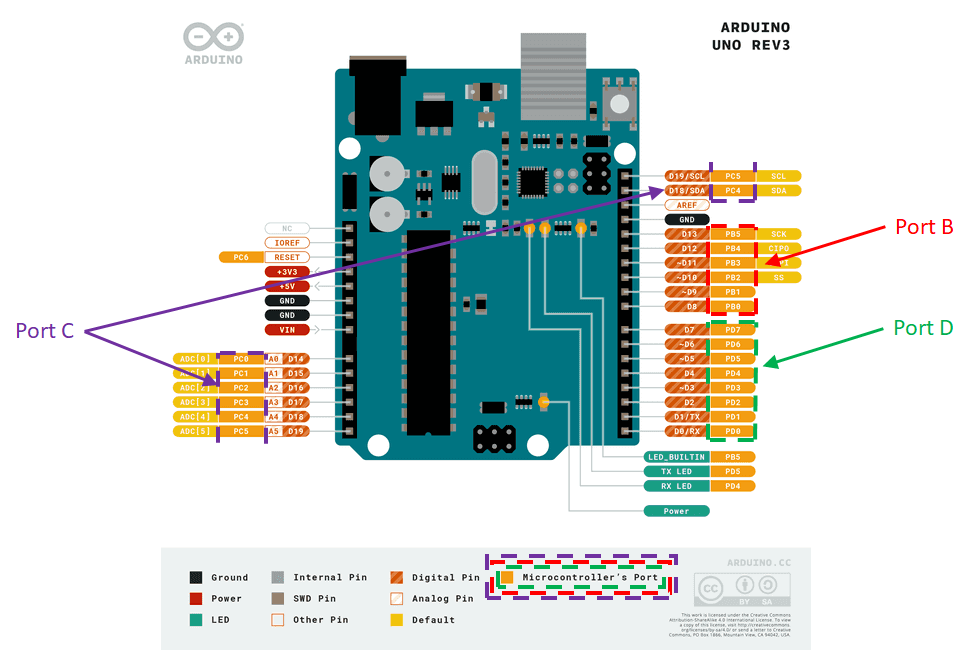
In this exercise, you will consider Port D pins on digital I/O D0 through D7, as illustrated in
Direct Hardware Register Configuration
This advanced method bypasses standard Arduino framework abstraction functions like attachInterrupt(). Instead, you will directly configure the microcontroller's low-level Control Registers (PCICR, PCMSK2), providing faster execution and lower interrupt overhead.
To implement Pin Change Interrupts (PCINT) on Port D, execute the following configuration steps:
- Pin Grouping: Identify the input pins to attach interrupts to, ideally selecting pins on a single 8-bit port to simplify state masking.
- Port Enable: Enable the Pin Change Interrupt Control Register (
PCICR) for the selected port bank. - Pin Masking: Select specific interrupt pins by updating the corresponding Pin Change Mask Register (
PCMSK2). - ISR Implementation: Write the dedicated Interrupt Service Routine vector (e.g.,
ISR(PCINT2_vect)).- Within the ISR, evaluate the port's current state against its previous state to determine which specific pin triggered the transition and increment/decrement position counters accordingly.
For a detailed walkthrough of register flags and hardware vectors, refer to the following article:
The principal advantage of direct register configuration is flexibility: almost any microcontroller pin can serve as an interrupt source, significantly expanding encoder channel capacity.
Consider a dual-encoder setup on an Arduino Uno:
- Encoder 1 (Left): Channel A \(\rightarrow\) Pin
D3, Channel B \(\rightarrow\) PinD4 - Encoder 2 (Right): Channel A \(\rightarrow\) Pin
D5, Channel B \(\rightarrow\) PinD6
As shown in PORTD and PIND registers), allowing a single ISR vector to service both quadrature encoders simultaneously.
The code snippet below outlines the basic register initialization sequence required to configure Pin Change Interrupts (PCINT) on Port D:
-
*Enable Port D Interrupt Bank: Activate the Pin Change Interrupt bit for Port D (
PCIE2) in the Pin Change Interrupt Control Register (PCICR): -
Clear Mask Register: Reset the Port D Pin Change Mask Register (
PCMSK2) to clear any residual bit configurations: -
Set Pin Interrupt Masks: Unmask digital pins
D3,D4,D5, andD6(PCINT19throughPCINT22) inPCMSK2:
Bitwise masking explicitly informs the microcontroller which digital pins must trigger the interrupt routine and which pins should be ignored. Masking unneeded pins prevents spurious interrupts from pin state toggles on unrelated I/O channels (such as serial UART communications on D0 and D1).
void setup()
{
  PCICR |= 0b00000100;
  PCMSK2 = 0;
  PCMSK2 |= 0b01111000;

}

void loop()
{
  // Put your main code here, to run repeatedly:
}

// This is the interrupt service routine for the Port D pin change interrupt
// Nore: you cannot define the name for this ISR
ISR (PCINT2_vect){

}
Interrupts are now enabled exclusively on the four encoder channels: pins D3 through D6. Whenever a logic edge transition occurs on any of these masked pins, the Interrupt Service Routine vector ISR(PCINT2_vect) automatically triggers.
Note: PCINT2_vect is the hardware Interrupt Vector location for `Port D** on ATmega microcontrollers and must be defined explicitly in your Arduino code.
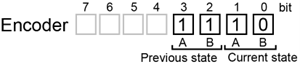
An efficient approach for decoding multiple quadrature encoders inside a single ISR is implementing a Lookup Table (LUT) state machine. The lookup table yields a direction value (\(+1\), \(-1\), or \(0\)) to increment, decrement, or leave the position counter unchanged by comparing the previous measured state against the current measured state of Channels A and B.To evaluate state transitions, construct a 4-bit composite state variable for each encoder structured as shown in
Using this encoding, one can create the following
Where: No = No rotation (current state = previous state), and NA = Not applicable (Impossible condition. Only one bit at a time can change)
Comparing Quadrature State Logic Tables
Analyse
Compare the corresponding rows between both tables to understand how the 4-bit composite state values in
The resulting 4-bit binary state variable yields a decimal index between \(0\) and \(15\) (\(2^4 = 16\) total state combinations). This index directly queries a lookup table (LUT) array containing the transition values (\(+1\), \(-1\), or \(0\)) derived from Column 5 of Table 4. It is essential to retain all 16 entries—including invalid or non-adjacent state transitions—to maintain fixed-array indexing boundaries.
The lookup table array is initialized as:
The complete implementation script, DualEncoderUsingPinChangeInterrupts.ino, below, demonstrates dual quadrature encoder decoding across digital pins D3, D4, D5, and D6 using Port D Pin Change Interrupts.
Procedure:
- Using the technique described above, modify your Arduino code that you wrote for Exercise 2 to use the pin change interrupt for a single encoder attached to pins D2 and D3.
- When you have this working, try changing the encoder connection pins and modify your script accordingly.
// Initialise the encoder counter variables
volatile long enc1_count = 0;
volatile long enc2_count = 0;

// Intialise a variable to to record the tick counter value
long tickValue = 0;

void setup() {

  PCICR |= 0b00000100;   // Activate the port D pin change interrupt on the
  // pin change interrupt control register
  PCMSK2 = 0;            // Reset the port D pin change mask
  PCMSK2 |= 0b01111000;  // Select the interrupt pins of interest from the
  // port D interrupt mask register

  // Define the pin modes dor D3, D4, D4, D6
  pinMode(4, INPUT);
  pinMode(5, INPUT);
  pinMode(6, INPUT);
  pinMode(7, INPUT);

  // Open the serial port at 9600 baud
  Serial.begin(9600);

  tickValue = millis();  // Record an initial tick counter value
}

void loop() {

  if (millis() >= tickValue + 100) {  // if 100ms has elapsed sine the last
  // time the followin code block ran

    tickValue = millis();  // Record the current tick counter value

    // Display the current encoder counter values on the serial monitor
    Serial.print("Encoder 1 Count = ");
    Serial.print(enc1_count);
    Serial.print("\tEncoder 2 Count = ");
    Serial.println(enc2_count);
  }
}

// This is the the interrupt service routine for the Port D pin change
// interrupt
// Note: you cannot define the name for this ISR
ISR(PCINT2_vect) {
  static const int8_t lookup_table[] = {
     0, -1, 1, 0, 1, 0, 0, -1, -1, 0, 0, 1, 0, 1, -1, 0 };
  // Byte that stores the current and previous state of the encoder outputs
  // for encoder 1
  static uint8_t enc1_val = 0;
  // Byte that stores the current and previous state of the encoder outputs
  // for encoder 2
  static uint8_t enc2_val = 0;

  // Shift the previous current encoder value to the pervious position
  enc1_val = enc1_val << 2;

  // The following line is a compound instruction:
  // Read prot D and use an AND mask to remove bit information, then Shift
  // the data relating to D3 and D4 to the first 2 bits. OR this with the
  // enc1_val register to form the 4-bit current and previous encoder variable
  enc1_Val = enc1_val | ((PIND & 0b00011000) >> 3);

  // Add the lookup table value relating to enc1_val to the encoder 1 counter
  enc1_count += lookup_table[enc1_val & 0b00001111];

  // Shift the previous current encoder value to the pervious position
  enc2_val = enc2_val << 2;

  // The following line is a compound instruction:
  // Read prot D and use an AND mask to remove bit information, then Shift
  // the data relating to D5 and D6 to the first 2 bits. OR this with the
  // enc1_val register to form the 4-bit current and previous encoder variable
  enc2_Val = enc2_val | ((PIND & 0b01100000) >> 5);

  // Add the lookup table value relating to enc2_val to the encoder 2 counter
  enc2_count += lookup_table[enc2_val & 0b00001111];
}
Bitwise Shift Operators
Bit-shift operators manipulate variables directly at the binary bit level:
- Right Shift (
>>): Shifts all bits in an integer to the right by a specified number of bit positions. For example,y = x >> 3;shifts the binary representation ofxthree positions to the right and assigns the resulting value toy. - Left Shift (
<<): Shifts all bits to the left by a specified number of bit positions (e.g.,y = x << 2;shifts the bits ofxtwo positions to the left).
Kinematic Conversion
After calculating the total encoder count, convert this value into encoder or motor output shaft revolutions, or angle, using the appropriate scaling constants.