Drive the Servo Motor Exercise
GTA Marking
This is an assessed Exercise. When you have completed the Assessed Exercise, you should show your work to a GTA to get marked.
Note
Before starting the software development for this exercise, you should ensure that you have completed the circuit on the robot chassis, as suggested on
The following video is a quick demonstration of the final outcome from this exercise:
Introduction
The aim of this exercise is to demonstrate the control of a position-control servo—specifically the MG90 servomotor. The MG90 is a low-power servo motor that can be driven directly from the Arduino board power supply.
Exercises:
Controlling a Standard Servomotor directly from the Arduino. (Informal Exercise)
Transitioning to MG90 Servo Motors
We are transitioning away from SG90 servos due to robustness issues and replacing these with MG90 servos. Some of you may still find that you have an SG90 servo in your kit – this is OK, you can use this device with same wiring, fixtures, and code.
The MG90 is a low-power servo motor and can be driven directly from the Arduino board power supply without requiring an external supply. However, if you attempt this with the MG996 servo, the current draw may be too large, causing voltage drops on the power supply lines that trigger an Arduino "
Note on the following Informal Exercise
This exercise is a legacy task from a previous iteration of the course and requires an standalone Arduino and an MG90 servo (i.e., not mounted on the robot chassis), as shown in
This exercise is not mandatory, but it provides an example sketch for operating a standard servo motor. The provided code is applicable to both the MG90 and the larger MG996, and it can serve as a foundation for the assessed exercise using the servo mounted on the robot chassis.
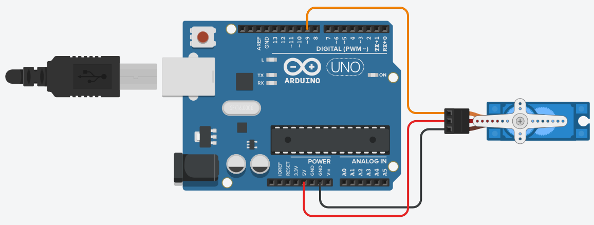
During this exercise, use the circuit shown in
- Red Wire: Positive power supply connection, connected to the \(+5\,\text{V}\) pin on the Arduino board.
- Brown Wire: Ground connection, connected to an Arduino GND pin.
- Orange Wire: (may be yellow) Pulse-Width Modulation (PWM) control line, connected to PWM-enabled digital pin 9 on the Arduino board.The orange wire is the control line and should be connected to a PWM enabled I/O pin on the Arduino board, in this example, pin 9.
Wiring Connection Tip
Connecting the lab's solid-core wires directly into the servo connector will result in a weak mechanical connection. While this connection is sufficient for this exercise, you can push male header pins into the breadboard to serve as an intermediate connection for improved mechanical stability.
Procedure:
- Connect the circuit as shown in
Fig. 2 . -
Copy the Standard_Servo_Example.ino sketch listed below:
Arduino code for the Standard_Servo_Example.ino Example
// This Example code is for use with the Controlling a Standard Servomotor exercise // // Include the servo library to allow for connection and control of servo motors #include <Servo.h> // define the macro pinServo1 as 9, to use for connecting the servo to pin 9 #define pinServo1 9 // Declare a servo motor class variable servo 1 Servo servo1; // ------------------------------------- // Setup function void setup() { // "attach" servo 1 to the defined pin servo1.attach(pinServo1); // set the neutral, centre, position for the servo servo1.write(90); // Alternte command for setting the neutral position //servo1.writeMicroseconds(1500); // wait until the servo has moved into position, (1000ms is more time than needed) delay(1000); } // ------------------------------------- // Loop Function void loop() { // start from the nuetral position, (90 degrees from the fully clockwise position) servo1.write(90); //servo1.writeMicroseconds(1500); // Alternate Command // wait until the servo has moved into position delay(1000); // move to 0 degrees, (fully clockwise) servo1.write(0); //servo1.writeMicroseconds(500); // Alternate Command // wait until the servo has moved into position delay(1000); // move to 180 degrees, (fully anti cloclwise position) servo1.write(180); //servo1.writeMicroseconds(2500); // Alternate Command // wait until the servo has moved into position delay(1000); } -
Looking at the code, above, you will see that the servo library had been included in the sketch. This external is library containing several functions that allow the Arduino to control a variety of servo motors. The Arduino reference library webpage for the servo library is located here:
https://www.arduino.cc/reference/en/libraries/servo/ Before you can use the servo control commands in your code, you must first perform the following operations in your code, (look at the code to see how this has been done):
- In the global scope:
- Include the servo library
#include <Servo.h> - Declare a servo motor object variable (e.g., Servo servo1;). This object is used by the Arduino environment to direct commands to a specific servo motor.
- In the
setup()function: - Link the servo motor object to an output pin using the 'attach()' method.
In 'Standard_Servo_Example.ino', we have declared a Servo object named
servo1, defined digital pin 9 as the control pin, and we attachedservo1to pin 9, using the following statement:servo1.attach(pinServo1);The servo motor is controlled using a Pulse-Width Modulation (PWM) signal. The active high duration of the PWM signal is typically bounded between \(1000\mu\text{s}\) and \(2000\,\mu\text{s}\), with a pulse repetition rate between \(40\,\text{Hz}\) and \(200\,\text{Hz}\) (a period between \(5\,\text{ms}\) and \(25\,\text{ms}\)).
The center or neutral position of the servo is commanded using a \(1500\mu\text{s}\) pulse width. Typically, the \(+90^\circ\) clockwise position is commanded with a pulse width of approximately \(500\mu\text{s}\), and the \(-90^\circ\) counter-clockwise position is commanded with a pulse width of approximately \(2500\mu\text{s}\). These \(90^\circ\) position pulse widths often vary slightly between servo models, so you may need to adjust these timings for your specific hardware.
The servo library has two functions for controlling the position of the servo:
write(): Commands the target angle directly in degrees.writeMicroseconds(): Commands a specific pulse-width duration in microseconds to the output pin.
The
write()function may not be precise for all servo motor models. You should evaluate the positioning accuracy of bothwrite()andwriteMicroseconds()for applications that require accurate output angles. -
Look at the Standard_Servo_Example.ino code, and see how the servo library has been used, how a servo is declared and attached to the system.
- Run the sketch and observe its operation
Controlling a Standard Servo with an External Power Supply
The previous exercise demonstrates how to connect and power a small servo directly from the pins of the Arduino board. When operating multiple small servos or larger servos, the Arduino's onboard power supply cannot satisfy the load requirements. This can cause the servos to malfunction or lead to unpredictable system behavior caused by a
This section describes how to power servos using an external power supply while maintaining control from the Arduino.
The SG90 is a low-power servo motor and can be driven directly from the Arduino board power supply, as shown in
To connect a larger servo to the system, you must use an external power supply to power the motor, as illustrated in
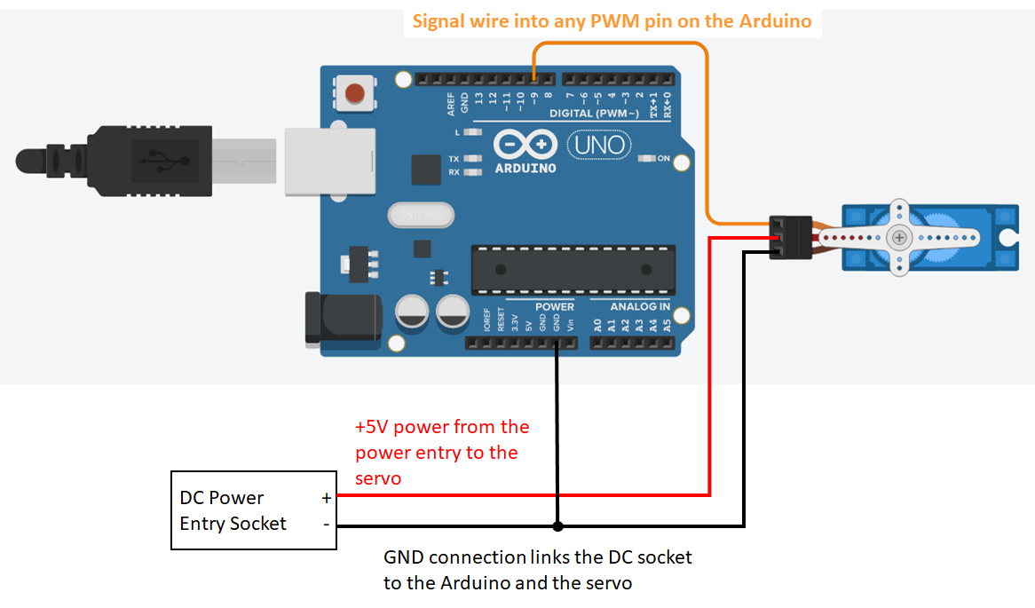
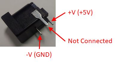
The pin connections for the external DC power jack (provided in the mechatronics kit box) are shown in
Linear mapping of a Value to a Measurement
In some cases, a sensor measurement can be linearly mapped from an input variable to a meaningful engineering value. In this exercise, you can map the analog-to-digital converter (ADC) measurement value from the potentiometer (ranging from \(0\) to \(1023\)) to a servo angle between \(90^\circ\) and \(0^\circ\) (representing the lolly stick between horizontal and vertical orientations).
The map() function provides linear calibration and scaling between an input measurement and a real-world parameter. In this exercise, you will pass the ADC measurement value as the input to the map() function and use its output to generate the position command for the servo motor.
map() Function Documentation
Refer to the map() function page from the Arduino Language Reference for a description:
Assessed Exercise: Driving the MG996 Servo on the front of the Robot Chassis
Before Starting This Exercise
Ensure that you have the servo and external power supply connected as described in the
The aim of this exercise is to demonstrate that you can operate a standard servo motor powered from an external supply and reset it to its neutral position.
Procedure:
- Before starting this exercise, remove the
lolly stick assembly from the MG996 servo on the robot chassis - Write a program to reset the servo motor to its neutral position using the command:
servo1.write(90); - While the servo motor is held in the neutral position, reattach the
lolly stick assembly , with the arm as close to horizontal as the servo shaft splines allow. - Write a second program (the assessed portion) to perform the following sequence:
- Upon reset or initial execution, the servo arm (lolly stick assembly) must move to the horizontal position.
- Note: You must tune the initial command angle in software to achieve true horizontal, as
servo1.write(90);alone may not align precisely.
- Note: You must tune the initial command angle in software to achieve true horizontal, as
- Maintain the horizontal position for \(1\,\text{s}\).
- Rotate the servo arm to the vertical position and hold it for \(1\,\text{s}\)
- Repeat the horizontal-to-vertical movement sequence once more.
- After an additional \(1\,\text{s}\) delay, continuously map the lolly stick angle to the potentiometer input:
- An ADC value from \(0\) to \(1023\) must map linearly to a servo command angle from approximately \(90^\circ\) down to \(0^\circ\) (corresponding to horizontal through vertical positions).
- Upon reset or initial execution, the servo arm (lolly stick assembly) must move to the horizontal position.
!!! !!! Note "Calibrating Servo Angles" You must adjust the mapped target angles to position the servo arm as close to horizontal and vertical as possible. A commanded servo demand of \(90^\circ\) is rarely perfectly horizontal, and \(0^\circ\) is rarely perfectly vertical.
Power Supply Requirement
The power supply for your servo MUST be provided by the external power supply and not from the Arduino \(+5\,\text{V}\) rail. The GND lines of the Arduino, external power supply, and servo motor must all be connected to the same ground node.
Danger: Risk of damage to your Laptop motherboard
If you connect the \(+5\,\text{V}\) pin of the Arduino board directly to the external power supply, you risk destroying your laptop's motherboard by sending a voltage spike back through the USB cable when the servo motor operates.
Please read the
The University of Sheffield and the Centre for Engineering Education (CEE) accept no responsibility for damaged personal devices caused by incorrect wiring. We strongly recommend using University IT equipment during practical sessions to mitigate the risk of damage to your personal devices.
Exercise Assessment
What we expect to see from your demonstration?
Your Servo must be powered from the external power supply during this exercise.
- When the Arduino is reset, or initially programmed, the servo arm (lolly stick assembly) should be set as close to horizontal as possible.
- You will need to adjust the initial angle of the servo in code to achieve this.
- The servo should wait 1 second before raising to as close to the vertical position as possible.
- The servo should wait 1 second before dropping to the horizontal position.
- The servo should wait 1 second before raising again to the vertical position.
- After 1 second, the servo should track the servo position, such that:
- When the potentiometer is in the far right position, the lolly stick is horizontal.
- When the potentiometer is in the far left position, the lolly stick is vertical.
- The lolly stick position tracks the potentiometer with a linear mapping.
Now Get Your Work Marked by a GTA
Once you have completed your code and are satisfied with its operation, you should show your work to a GTA for marking.