Getting Started - Introductory Exercises (Non-assessed)
The Arduino IDE
This guide provides a brief overview of installing and configuring the Arduino Integrated Development Environment (IDE) for your laboratory activities. Two introductory exercises accompany this section to guide you through compiling and uploading code to the Arduino microcontroller, as well as working with basic digital inputs and outputs.
The Installing and Using the Arduino IDE on a University Managed PC
The Arduino IDE is pre-installed on workstations across the Electronics and Control Laboratory. If you are using a managed PC in another area of The Diamond or across the wider university campus, you can install the software directly via the Software Centre application.
Administrative Restrictions
Students do not have administrator rights on university-managed desktop PCs and cannot download or run executable installers directly from the web. Always use Software Centre for software installation on campus hardware.
Installation and Setup of the Arduino Software on your own
Scope Notice
The installation steps below apply only to setting up personal home computers or laptops. All university laboratory PCs already have the required software pre-configured.
Please note that all module documentation, drivers, and laboratory instructions are written for Windows 10 and 11 (64-bit). The course team cannot provide technical support for other operating systems.
For official installation instructions, board package setup guides, and software downloads, visit the official
Procedure:
- Download and Install Arduino IDE: Download the Windows installer package from the official debugHL>hhttps://www.arduino.cc/en/software/ and complete the setup wizard.
- Verify IDE Installation: Launch the Arduino IDE to verify that the application opens cleanly without initialization errors.
- Ensure the correct board core package is installed to support the ATmega328P microcontroller:
- Open the Boards Manager via Tools \(\rightarrow\) Board \(\rightarrow\) Boards Manager... (or click the Board Manager icon in the left-hand sidebar).
- Search for Arduino AVR Boards.
- Verify that the package is installed. If an update is available, select the latest version from the drop-down menu and click Update.
-
Connect Hardware and Select Target Port: Connect your Arduino Uno board to your computer via USB (using an inline USB isolator on personal laptops) and configure the target device settings:
- Go to Tools \(\rightarrow\) Board \(\rightarrow\) Arduino AVR Boards and select Arduino Uno.
- Go to Tools \(\rightarrow\) Port and select the active communication port corresponding to your connected board (e.g., COM3 or COM4 on Windows).
For detailed board selection and driver troubleshooting, refer to the official Getting Started with
Arduino Uno Guide .
Laboratory Exercises
Simple Digital I/O
Note
The following exercises provide an introductory, step-by-step tutorial on compiling and uploading basic code via the Arduino IDE. They are specifically designed for students with no prior microcontroller experience.
Microcontrollers serve as the core embedded controller in many mechatronic and robotic systems. In these introductory exercises, you will interface basic digital input components (such as tactile push buttons) and digital output components (such as Light Emitting Diodes).
These digital components demonstrate fundamental sensor-actuator control loops: an user-initiated input event (e.g., depressing a push button) triggers software execution that modifies system output state (e.g., toggling an LED indicator).
Note
Before starting the laboratory exercises, review the documentation inside the Mechatronics Kit Information directory under the Lab Practicals (Sem 1) area on the Blackboard site.
Intro Exercise 1: Blink Example
The aim of this exercise is to demonstrate how to compile, upload, and run a simple program on the Arduino Uno hardware..
Executing the built-in "Blink" sketch verifies that your software environment and toolchain are configured correctly while confirming hardware functionality and USB communication.
Procedure:
- In the Arduino IDE, navigate to File \(\rightarrow\) Examples \(\rightarrow\) 01.Basics \(\rightarrow\) Blink as shown in
Fig. 1 :
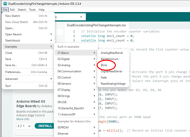
Built-in Examples
The built-in examples provided within the Arduino IDE offer a valuable repository of reference implementations demonstrating hardware control, peripheral interfacing, and C programming constructs.
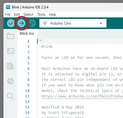
- To compile and upload the sketch to your connected Arduino board, click the Upload button (the right-pointing arrow icon) located on the top toolbar, as shown in
Fig. 2 :
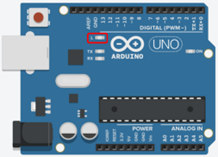
After the Arduino IDE finishes compiling and uploading the sketch, the microcontroller automatically executes the program. For the Blink sketch, successful execution is indicated by the onboard status LED, labeled "L" (highlighted in red in
- The setup() and loop() functions for the Blink sketch are shown below:
// the setup function runs once when you press reset or power the board
void setup() {
  // initialize digital pin LED_BUILTIN as an output.
  pinMode(LED_BUILTIN, OUTPUT);
}

// the loop function runs over and over again forever
void loop() {
  digitalWrite(LED_BUILTIN, HIGH);  // turn the LED on (HIGH is the voltage level)
  delay(1000);                      // wait for a second
  digitalWrite(LED_BUILTIN, LOW);   // turn the LED off by making the voltage LOW
  delay(1000);                      // wait for a second
}
Modify the integer arguments inside the delay() calls (e.g., change 1000 to 200 or 2000), compile, and upload the updated sketch to your board. Observe the state changes on the onboard LED "L".
(For detailed function syntax, input parameters, and execution limitations of the delay() function, consult the official
Intro Exercise 2: Push Button and LED
The aim of this exercise is to interface a digital input device (a tactile push button switch) to control a digital output actuator (a Light Emitting Diode).
Wiring Procedure:
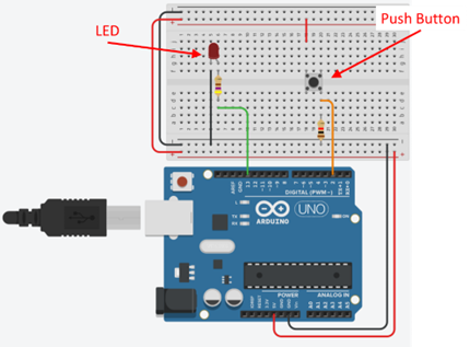
- Using the components provided in your Mechatronics lab kit, assemble the circuit shown in
Fig. 4 on your breadboard according to the following specifications:- Digital Input (Push Button): Connect one side of the push button switch to digital pin 2 on the Arduino Uno. Connect a \(10\,\text{k}\Omega\) pull-down resistor between digital pin 2 and the GND rail to ensure a stable low state when the button is unpressed.
- Digital Output (LED): Connect digital pin 13 on the Arduino Uno to the anode (longer leg) of the LED through a \(470\,\Omega\) current-limiting resistor. Connect the cathode (shorter leg) of the LED directly to the GND rail. (Note: Digital pin 13 is shared with the onboard status LED "L").
- Power Connections: Connect the 5V and GND header pins from the Arduino Uno to the power distribution rails of your breadboard.
Wire Color Coding
While wire insulation color does not affect electrical functionality, adhering to standard color conventions (e.g., Red for 5V, Black for GND) improves circuit readability and simplifies troubleshooting during lab practicals.
Pull-Down Resistor Operation
Digital pin 2 is tied to the \(0\,\text{V}\) (GND) supply rail through a \(10\,\text{k}\Omega\) pull-down resistor.
When the button is pressed, pin 2 is connected directly to the \(+5\,\text{V}\) rail, driving the input state HIGH. When the button is released, the \(10\,\text{k}\Omega\) resistor drains remaining charge and pulls the input voltage back down to \(0\,\text{V}\) (LOW). Without this pull-down resistor, the input pin would "float" in a high-impedance state, picking up electromagnetic noise and causing unpredictable or spurious input readings.
To open the sketch for this exercise within the Arduino IDE, navigate to:File \(\rightarrow\) Examples \(\rightarrow\) 02.Digital \(\rightarrow\) Button
Procedure:
- Compile and Upload: Click the Upload button to compile and upload the Button sketch to your Arduino board.
- Verify Circuit Operation: Press and hold the push button. The external LED (and onboard LED "L") should illuminate immediately. Release the push button; the LED should extinguish.
Serial Data Logging and Debugging
In embedded system development, monitoring runtime variable values and diagnostic messages is essential for verifying software execution. Using the built-in Serial library, the Arduino streams ASCII text data over its hardware UART line and USB connection (utilizing the same Virtual COM port used to flash firmware). You can observe this real-time data stream directly using the Serial Monitor terminal in the Arduino IDE.
The modified Button example code,
// constants won't change. They're used here to set pin numbers:
const int buttonPin = 2;  // the number of the push button pin
const int ledPin = 13;    // the number of the LED pin

// variables will change:
int buttonState = 0;  // variable for reading the push button status

void setup() {
  // Initialise communications with the serial monitor. Parameter: baud rate
  Serial.begin(9600);

  // initialize the LED pin as an output:
  pinMode(ledPin, OUTPUT);
  // initialize the push button pin as an input:
  pinMode(buttonPin, INPUT);
}

void loop() {
  // read the state of the push button value:
  buttonState = digitalRead(buttonPin);

  // Write the value of the buttonState variable to the serial monitor
  Serial.println(buttonState);

  // check if the push button is pressed. If it is, the buttonState is HIGH:
  if (buttonState == HIGH) {
    // turn LED on:
    digitalWrite(ledPin, HIGH);
  } else {
    // turn LED off:
    digitalWrite(ledPin, LOW);
  }
}
These additional commands perform the following operations:
-
Serial.begin(9600);: Configures the microcontroller's hardware serial peripheral and sets the communication speed to 9600 baud (bits per second). This must be called inside the setup() function. -
Serial.println(buttonState);: Formats the integer value of buttonState as text and transmits it across the COM port, terminating the line with a carriage return and line feed (\r\n).
For complete syntax documentation and related peripheral drivers, see the Arduino Serial Reference Guide
Launching the Serial Monitor
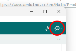
To open the Serial Monitor console within the Arduino IDE, click the Serial Monitor icon (magnifying glass icon in IDE 1.x or the terminal icon in IDE 2.x) located in the upper-right corner of the window, as shown in Figure 5.
Links to all the Serial function descriptions are listed towards the bottom of the
To open the Serial Monitor, from the Arduino IDE, click the button in the top right of the IDE, as highlighted in
Procedure:
- Update and Upload the Sketch: Add
Serial.begin(9600);tosetup()andSerial.println(buttonState);toloop(), then click Upload to program the Arduino Uno. - Launch the Serial Monitor: Click the Serial Monitor button in the top-right corner of the Arduino IDE interface (or press Ctrl + Shift + M). Ensure the baud rate drop-down menu in the bottom-right of the terminal is set to 9600 baud.
- Observe Output Stream: Observe the output console while interacting with the hardware:
- Button Released: The Serial Monitor prints continuous streams of 0.
- Button Pressed: The output state transitions instantly to 1.